Chipboard Beam Rules
Beam Construction Rules
- Beams must be constructed using standard medium-weight chipboard panels. Card-board
consisting of a fluted corrugated sheet and one or two flat linerboards is not ac-ceptable.
The chipboard can be cut and glued together to develop any section required by the
design team. Individual chipboard panels should have a thickness between 0.050 and
0.100 inches. Figure 1 shows typical 12 in. x 12 in. x 0.05 in. chipboard panels.

Figure 1. Medium-weight chipboard panels - Any type of glue is allowable; however, it is recommended to use an inexpensive water-based
glue.
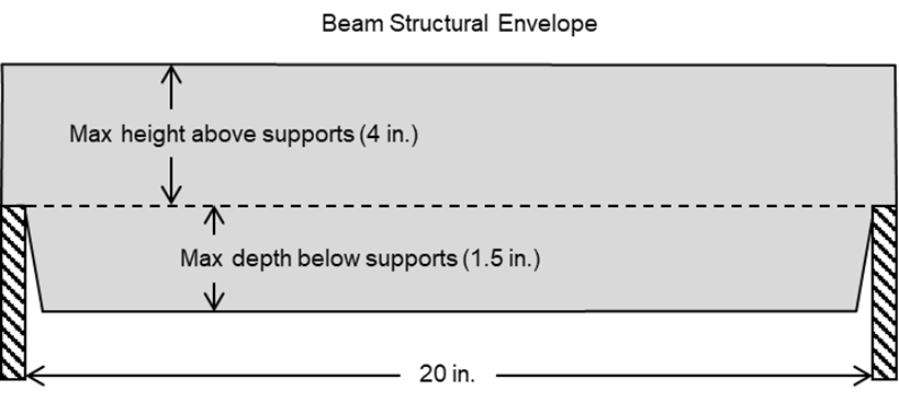
- The beam must be designed to fit on the support shown in Figure 2. Beams may be sup-ported
only off the top surfaces of the supports. Members may not brace off the sides of
the horizontal bottom of the support.

Figure 2. Bridge supports and geometrical constraints - The beam must span an opening of 20 in. It is recommended that the beam be at least
22 in. in length to ensure that the beam meets the span requirements and extends over
the supports,
At any point along the beam, the minimum width of the beam is 2 in., and the maximum width of the beam is 4 in.
Once the beam is placed on the supports, no portion of the beam may extend more than 4 in. above the supports or 1.5 in. below the supports. The beam must fit into the gray-shaded structural envelope, as shown in Figure 2. - The beam may be built up for multiple layers of chipboard to form any thickness and
shape required for the design within the tolerances stated in Item 4 and shown in
Figure 2. Individual chipboard sheets cannot be coated or treated in any way except
when glued together.
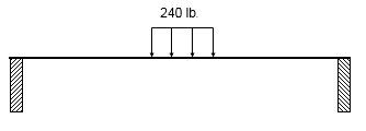
- Each beam must support 240 lb. distributed over 6 in. at the center of the bridge
(see Figure 3). Failure is defined as collapse or maximum deflection (> 1.5 in.) resulting
in contact between the bridge and the horizontal base of the support. If your beam
cannot support the 240 lb. design load, your beam is disqualified from the competition.

Figure 3. Uniformly distributed load - The shape and dimensions of the cross-section of the beam may vary along the beam
as long it fits into the beam structural envelope shown in Figure 2.
- If the beam supports the 240 lb. design load, then its performance will be measured by the SWR. The team with the highest SRW will win the competition.
If you have any questions about this competition, please contact Dr. Charles Camp, cvcamp@memphis.edu.

